Home | Photos | Links | Pocket PC | Vintage computing | Contact
CE-124 modification for CE-124FIRE
CE-124FIRE is a device based on M5Stack FIRE and created by @nomatan373. The original instructions at pocketpc.f5. @nomatan373 created his own 11 pin connector but I had the idea to modify an original Sharp CE-124 to replace the 3D printed connector.
CE-124 are still offered as used hardware at the usual websites and the one I used for this modification cost only 10 € including shipping fees!
The first step was to open it, remove the PCB from the case and then the parts from the PCB. After that, the exact dimensions of the 0.8 mm thick PCB were measured and entered in KiCad. @nomatan373 used only three parts, the connector and two 220 kOhm resistors, so there wasn't any need to draw a schematic.
I wanted to save myself the hassle to crimp the connector for the M5StackFIRE, so I bought M5Stack's HY2.0-4Pin Cable. I chose the 100 cm length so I could make 2 cables. I also bought the small rubber thingies called cable gland. Unfortunately, the sellers documentation wasn't clear enough for me, so I had to drill a bigger hole into it, because of the cable with the braided sleeve I used.
Anyway in the end it fitted nice and worked perfectly.
VERY IMPORTANT:@nomatan373's cable has white and yellow connected differently than the original grove cable that M5Stack sells. The colours that are printed on the PCB are meant for the MStack cable. Please check the correct connection before using it.
If you are a Pocket PC enthusiast that owns a CE-124FIRE and want to modify your CE-124, write me a short message and if there are any left, I'll send you a PCB for free. Of course you can make your own PCB using my KiCad project, but remember to order 0.8 mm thick PCBs:
CE-124FIRE-cable.zip (657.3KiB)
If you have questions or found any errors feel free to contact me!
Photo documentation
I took some photos along the modification process. With the PCB design done, the only thing that took some effort is to create a nice cable.
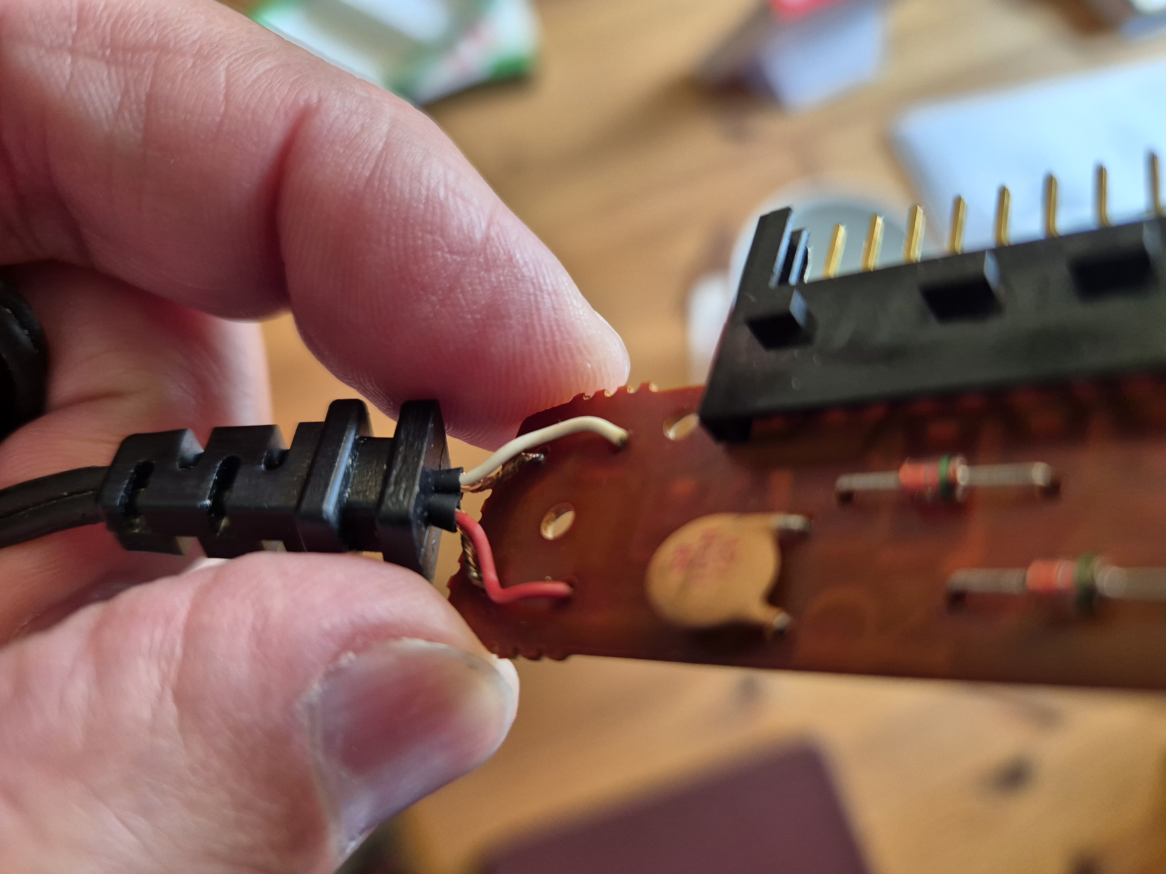
Image 1
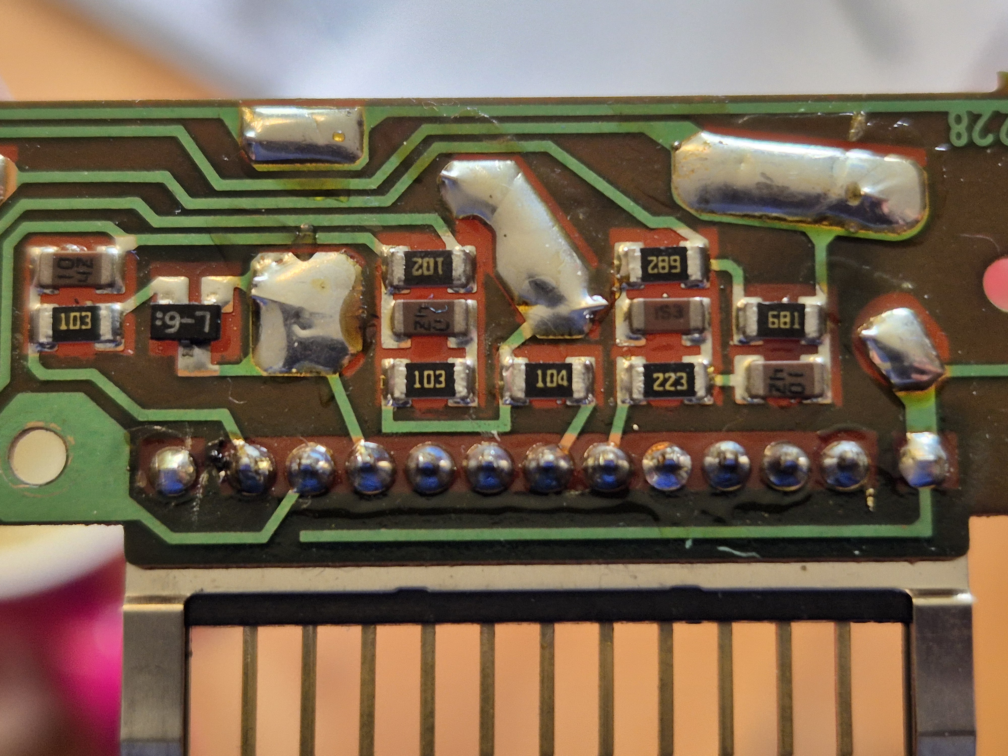
Image 2
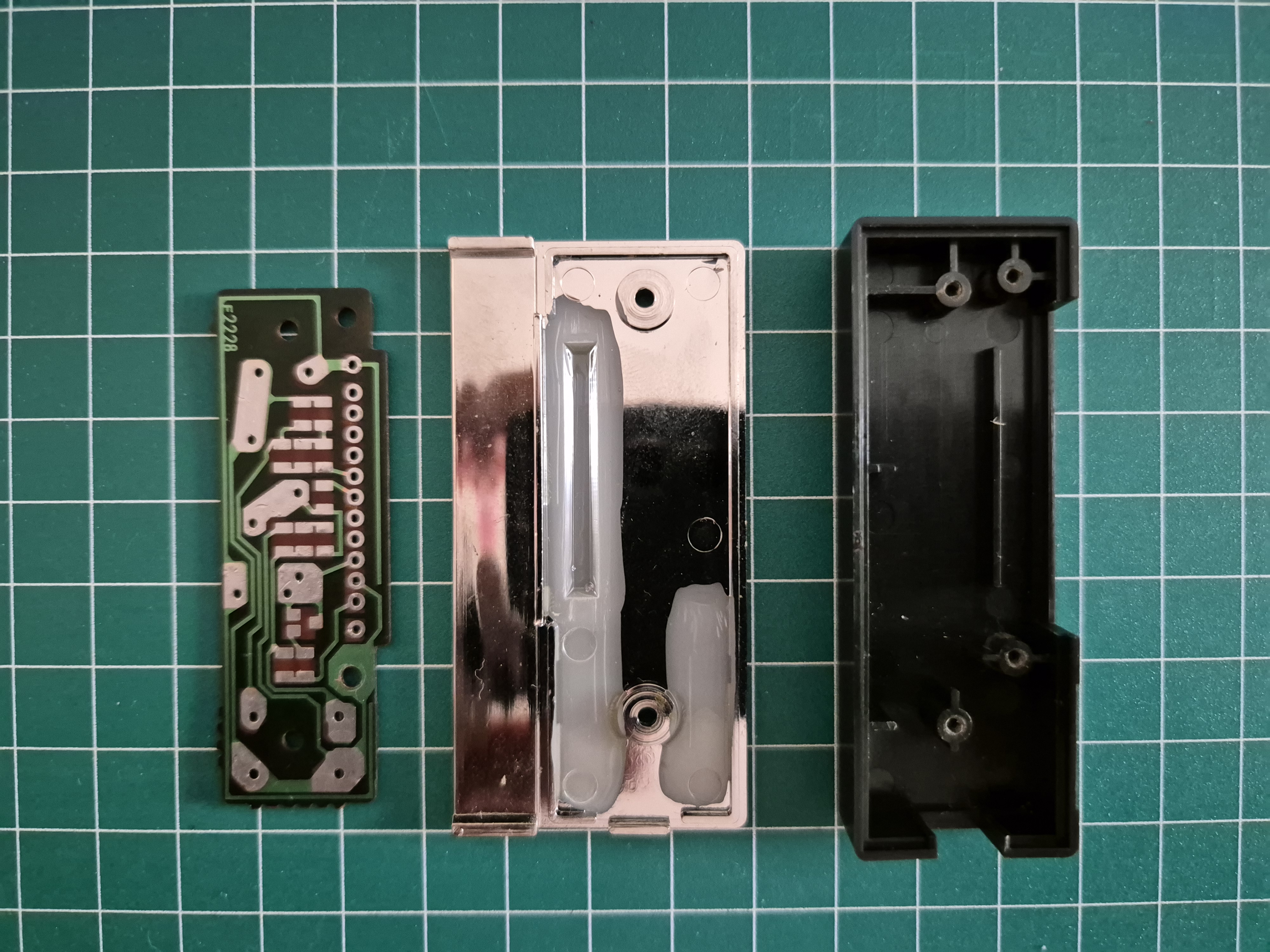
Image 3
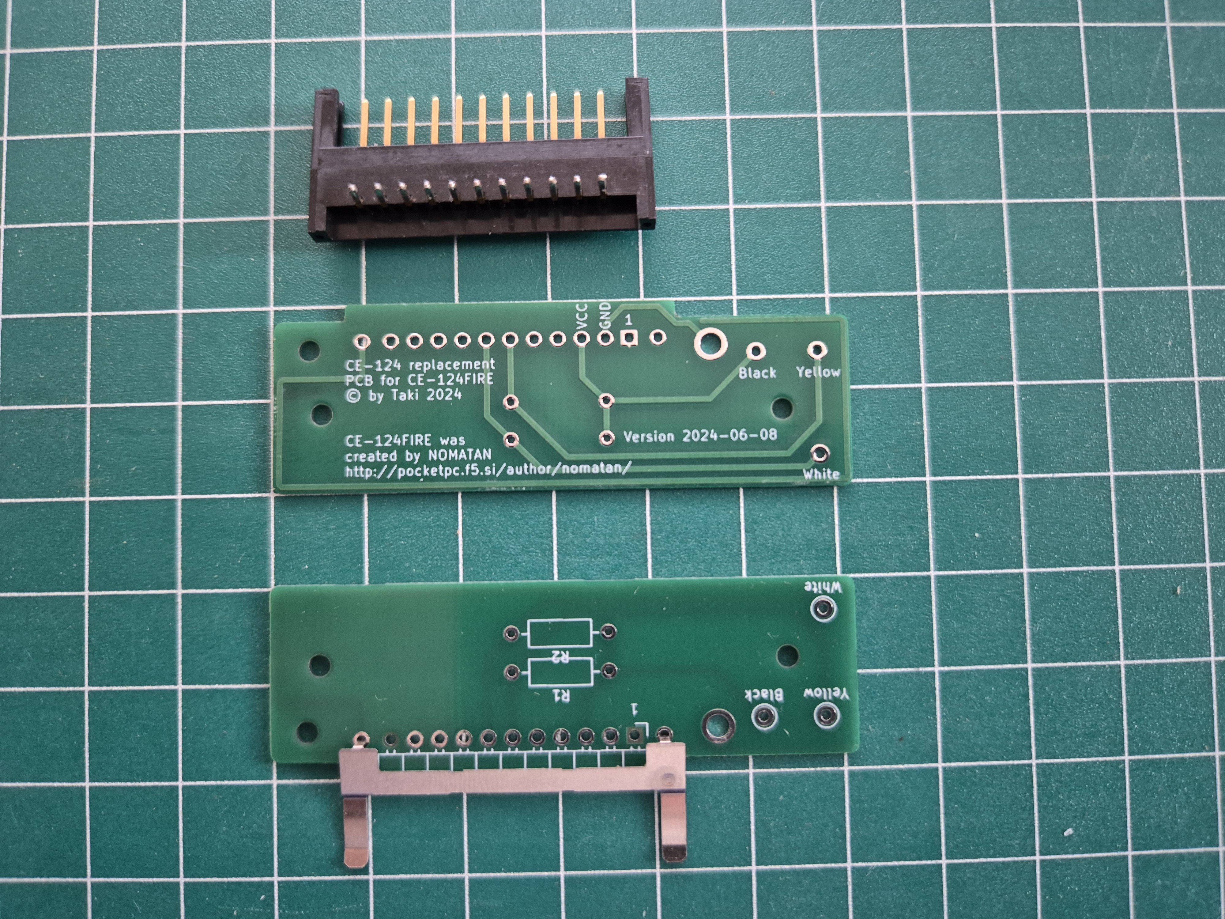
Image 4
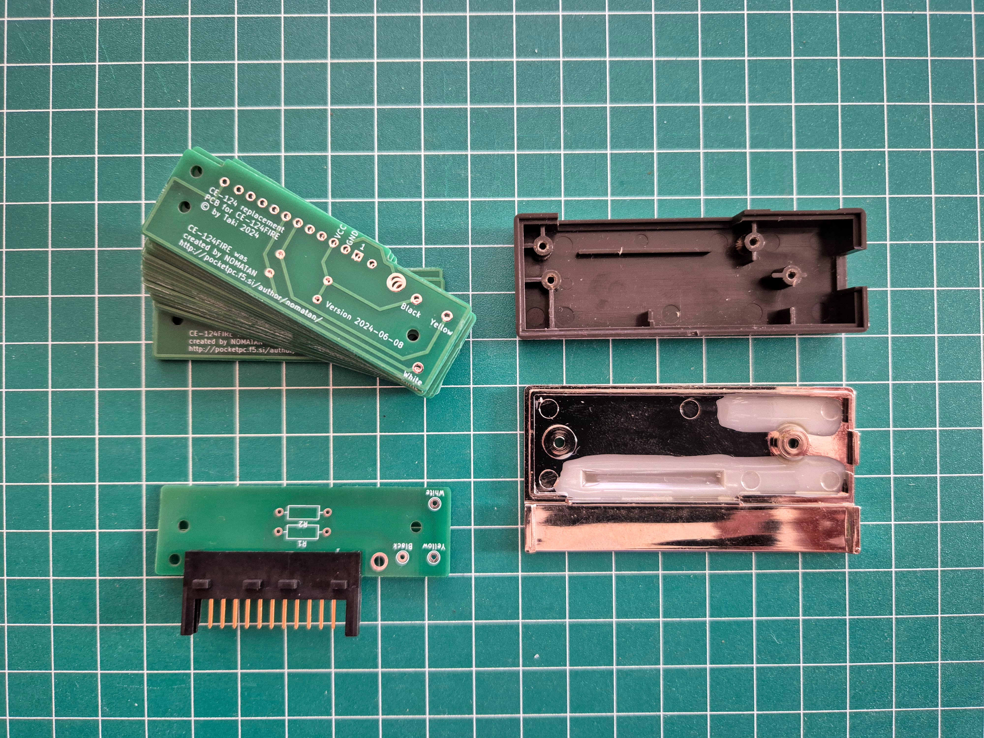
Image 5
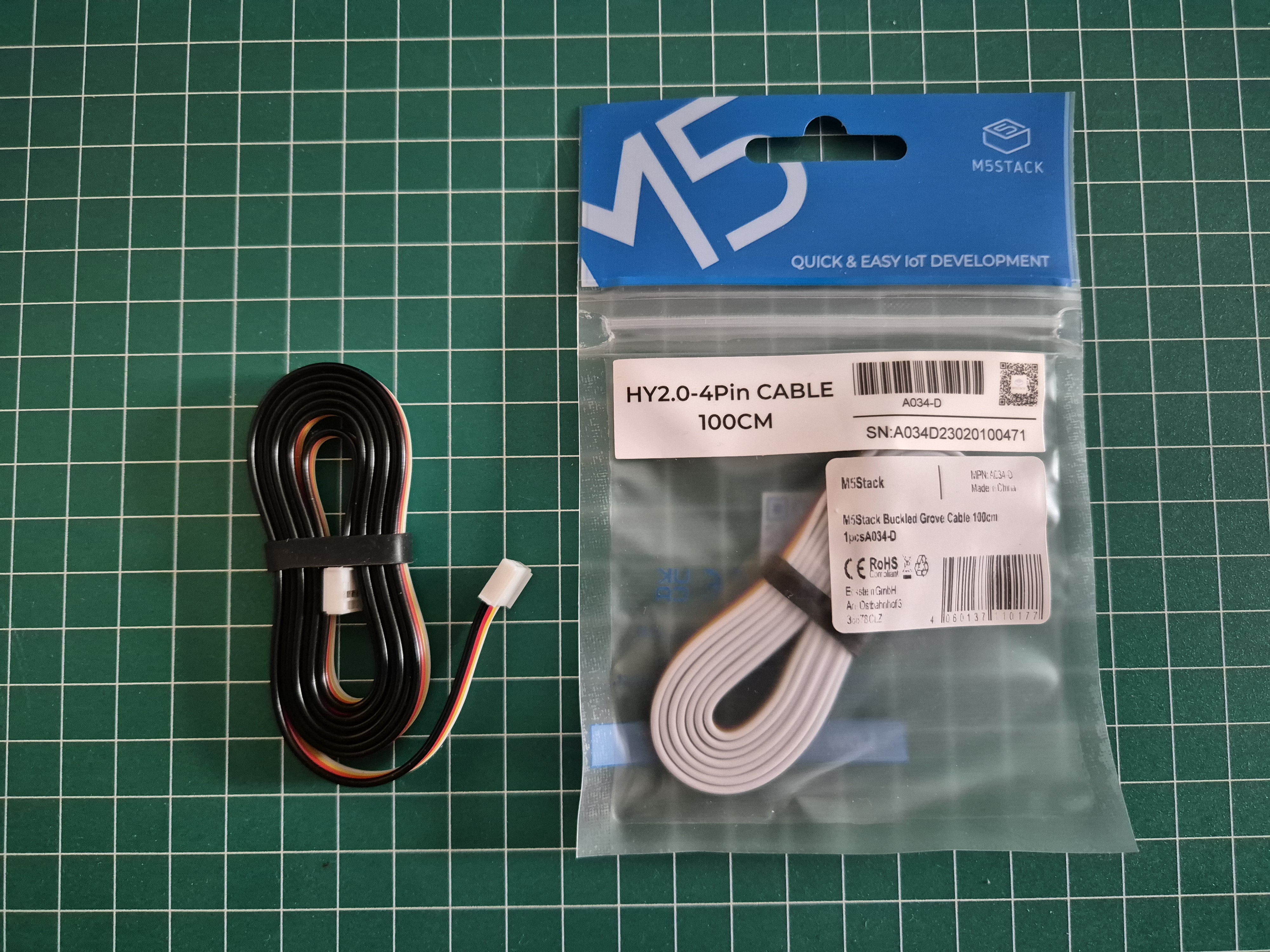
Image 6
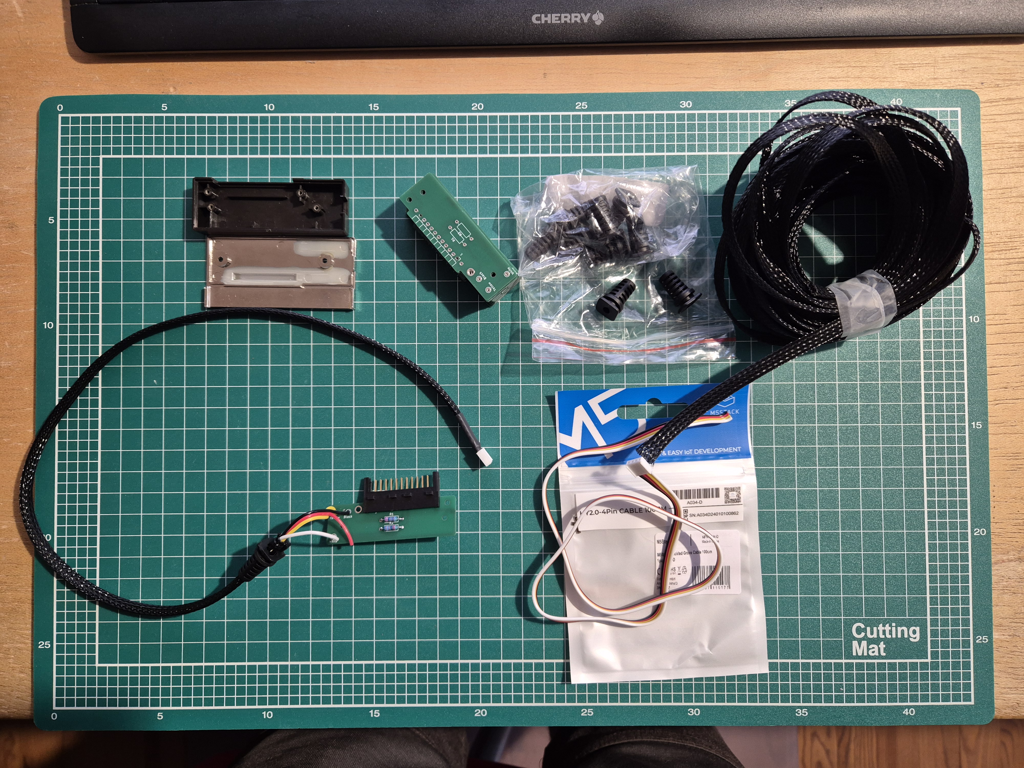
Image 7
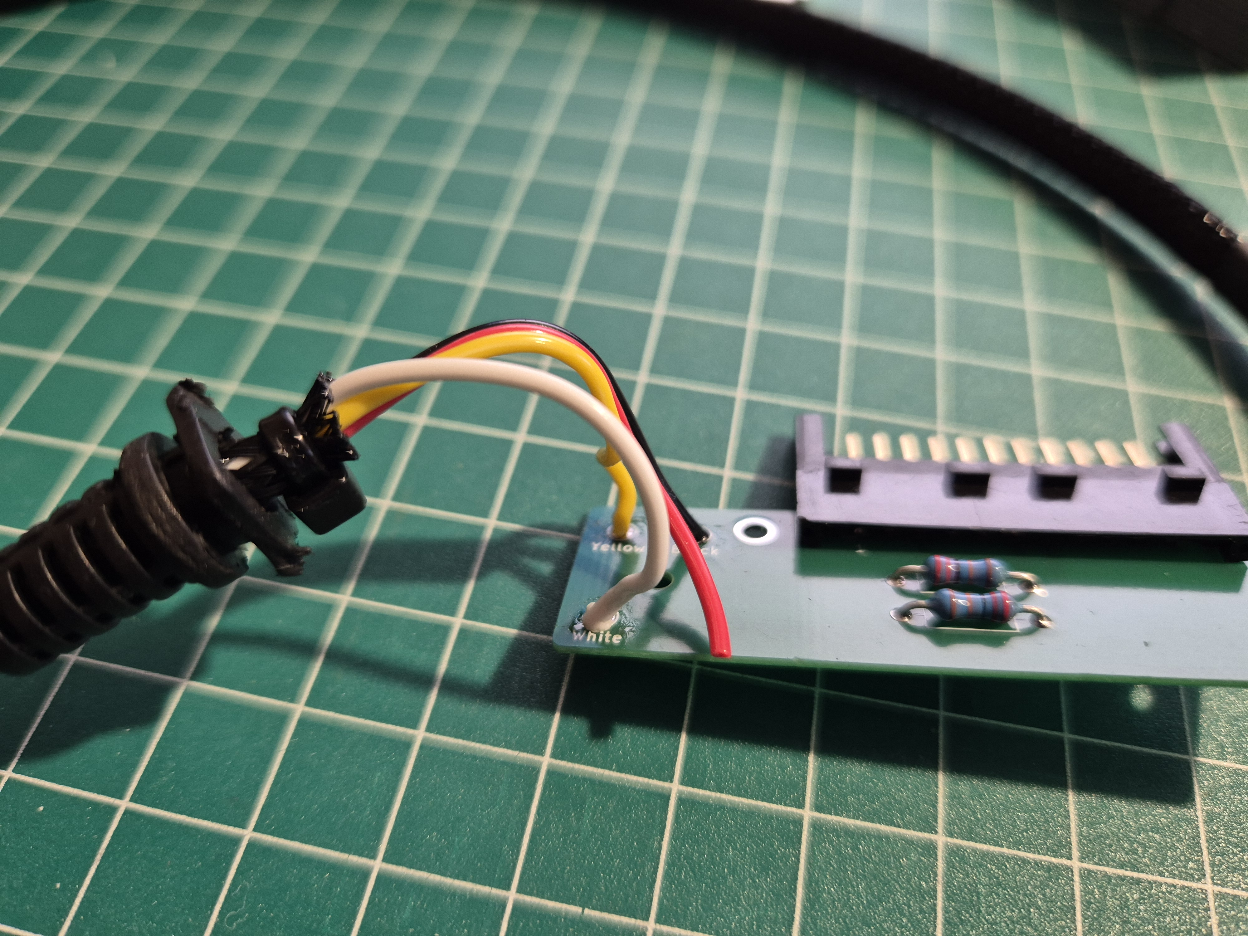
Image 8
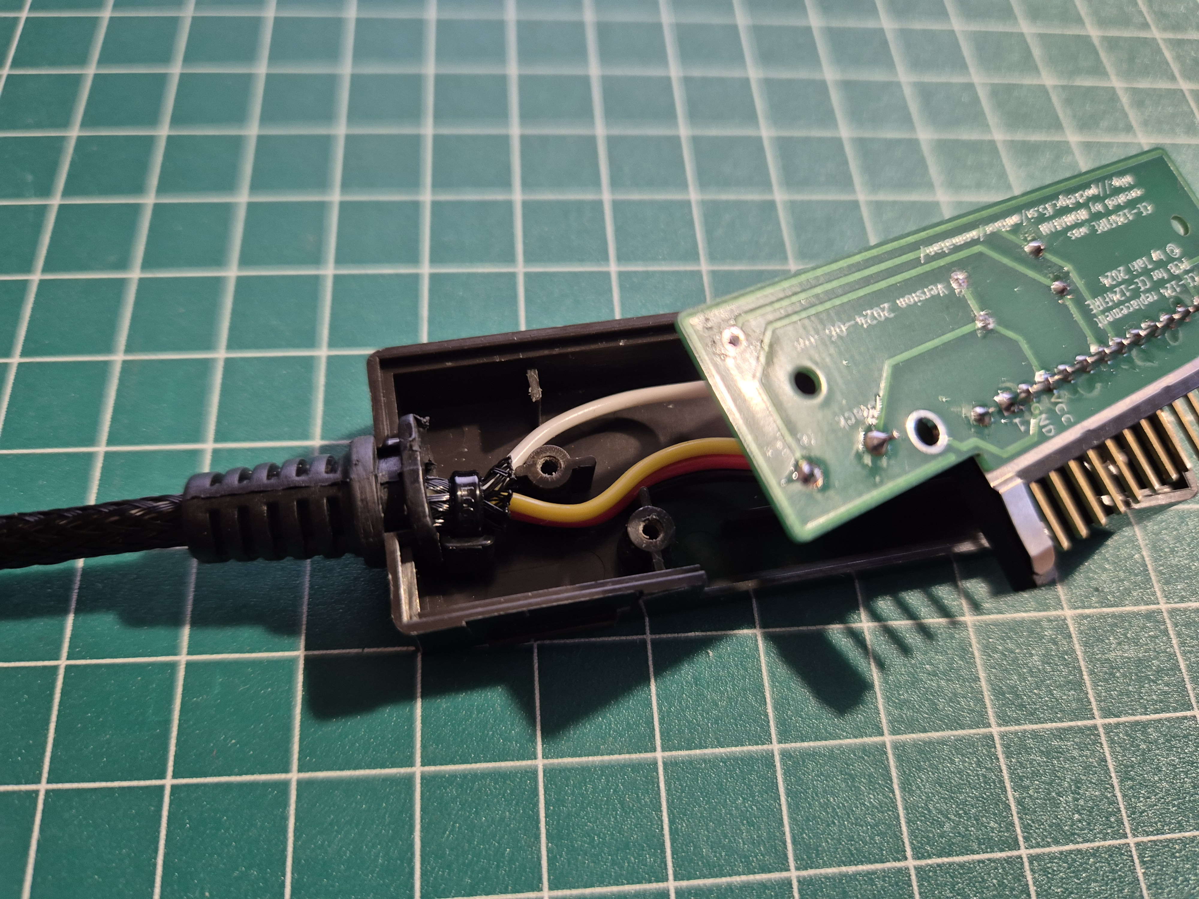
Image 9
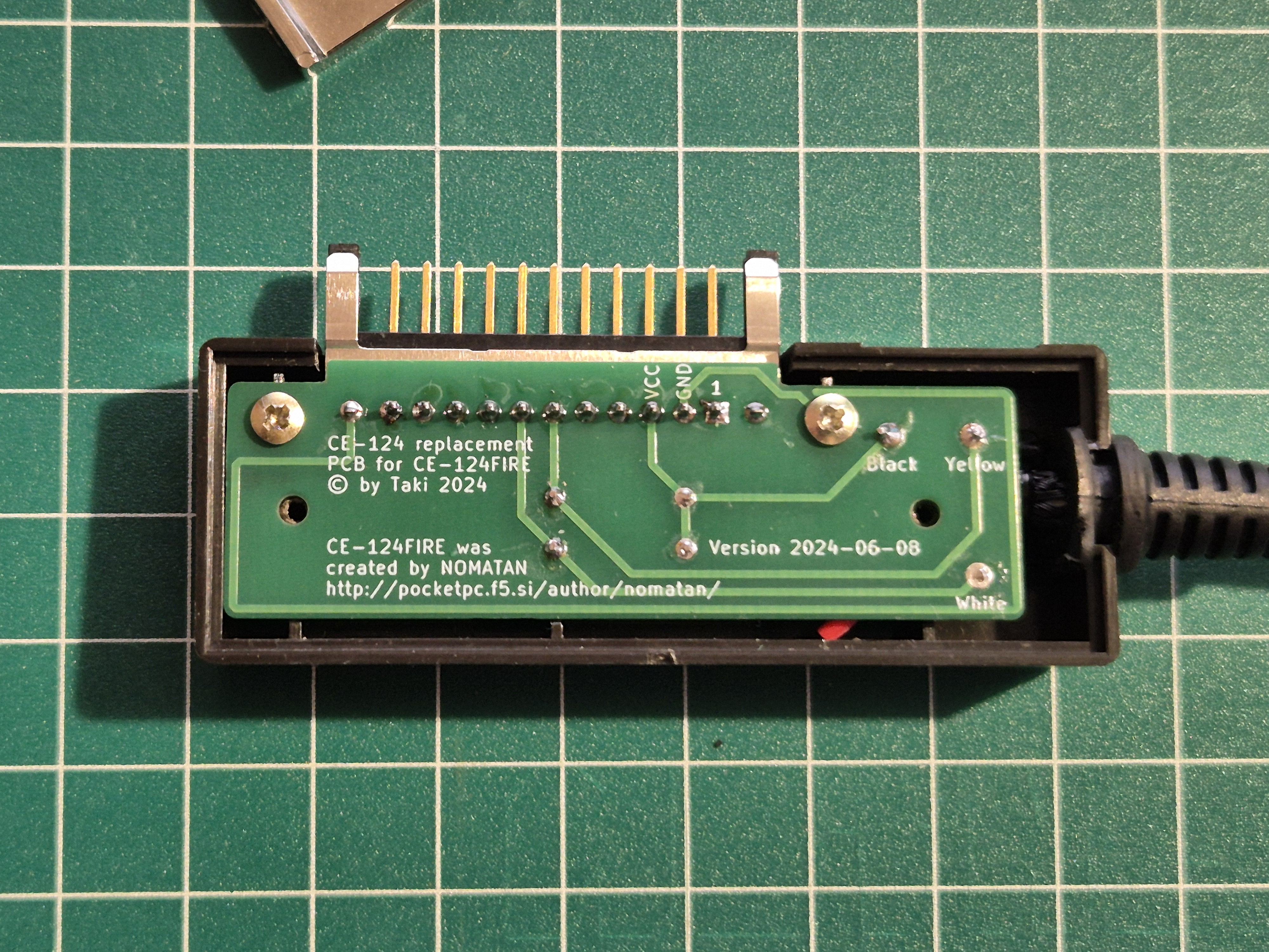
Image 10
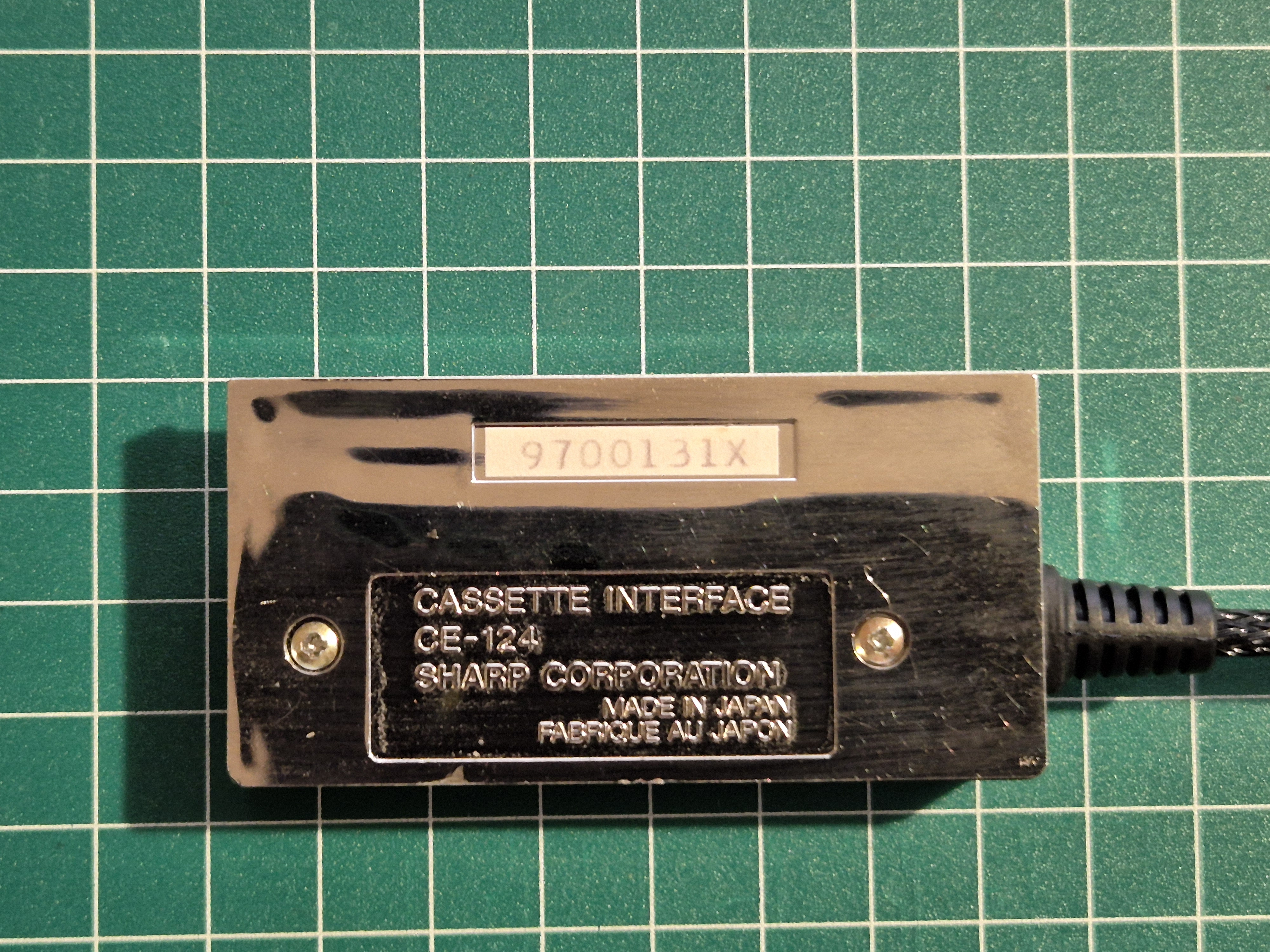
Image 11